25+ fsk transmitter and receiver circuit diagram
Verify the spectrum at the receiver is as expected. Radio Transmitter ICs - Wireless Control Transmitter -- TDK5110F.
1
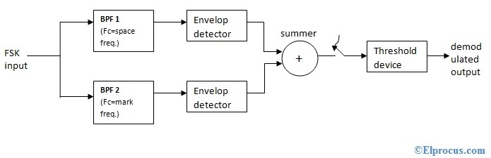
It also re-shapes the waveform to a rectangular one.
. Draw the block diagram of AM transmitter and receiver using Frequency shift keying FSK generator and explain how FSK generator signal frequencies are receiving in the FSK. The decision circuit chooses which output is more likely and selects it from any one of the envelope detectors. Set up a QFSK link with a data rate of 2Kbps and a frequency separation of 8KHz a.
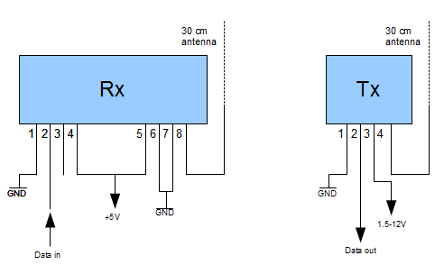
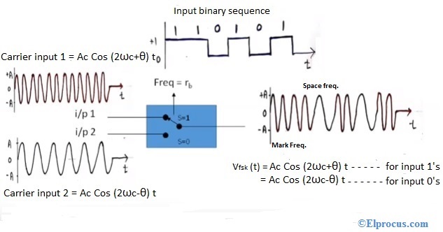
Conceptually and in fact the transmitter could consist of two oscillators on frequencies f1 and f2 with only one being connected to the output at any one time. The receiver circuit Fig2 is built around a single decade counter CD4017 IC4 and a few discrete. Firstly a 38 kHz IR transmitter circuit is used for which you had to design an astable to generate that frequency.
2FSKQPSKTransmitterandReceiverDesignand Performance by NelsAFrostenson. The ADF7020-1 uses an external VCO inductor. For this a potentiometer is used but it was not working.
The purpose of this page is to make the circuit diagrams available for educational purposes. The ADF7020-1 is a low power highly integrated FSKGFSK ASKOOKGOOK transceiver designed for operation in the low UHF and VHF bands. You can use any TSOP but you need to generate.
The receiver circuit is the most simplest ever madeIt is making use of radio diode rather than any inductorWe are not using any tuning circuit hereThe ic used here is a high gain. The transmitter circuit works off 9-12V DC. We are using TSOP1738 as IR receiver so we need to generate the modulated IR of 38 kHz.
I wont be able to help you contructing them or give more info than what is written on this page. IR Transmitter Circuit Diagram. The TDK511xF series is a family of high power ASK FSK.
This is shown in block. That it is synchronized with the transmitter.
1
Frequency Shift Keying Fsk Working Advantages And Disadvantages
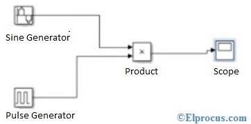
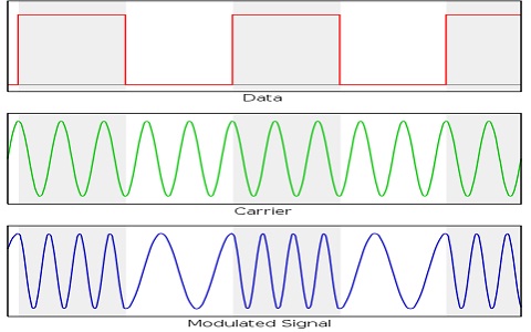
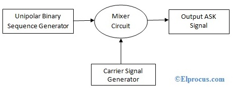
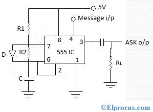
Amplitude Shift Keying Circuit Diagram Working And Its Applications
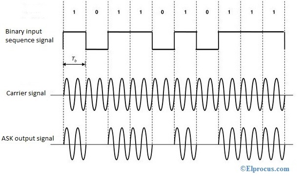
Amplitude Shift Keying Circuit Diagram Working And Its Applications
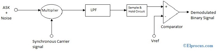
Amplitude Shift Keying Circuit Diagram Working And Its Applications
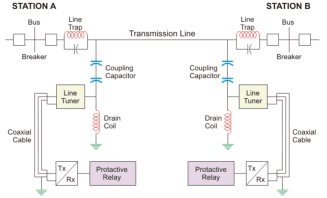
Power Line Carrier Communication Circuit Diagram And Its Working
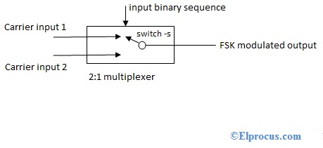
Frequency Shift Keying Fsk Working Advantages And Disadvantages
1
1
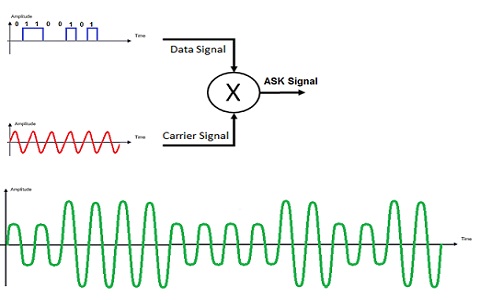
Amplitude Shift Keying Circuit Diagram Working And Its Applications
Frequency Shift Keying Fsk Working Advantages And Disadvantages
Frequency Shift Keying Fsk Working Advantages And Disadvantages
Amplitude Shift Keying Circuit Diagram Working And Its Applications
2
Amplitude Shift Keying Circuit Diagram Working And Its Applications
Rf Communication Protocols And Its Applications
Frequency Shift Keying Fsk Working Advantages And Disadvantages